Question
Is there a convenient means of testing my piezoresistive pressure transducers, such as the Endevco model
8510C series?
Answer
One of the advantages of piezoresistive devices is that the user can analyze the health of these sensors using a simple digital multimeter. This paper will cover proper testing procedures for devices supplied with precise resistance measurement data on calibration certificates, as well as for those supplied without such data.
General considerations
Endevco piezoresistive pressure transducers feature an active four-arm strain gage (gauge) Wheatstone bridge design, diffused into a sculptured silicon diaphragm, for maximum sensitivity and wideband frequency response. They are also temperature compensated for greater performance stability. While the bridge resistors will drift with temperature, compensation resistors reduce this drift substantially by as low as 30 Ohms over the compensated temperature range. Because of the temperature compensation, actual bridge input and output resistance values will show little deviation from listed calibration certificate values.
As piezoresistive transducers are somewhat ratiometric, it is essential to ensure careful and accurate excitation voltage control. For best results, it is highly recommended to test these devices within a laboratory environment, in an area away from air conditioning drafts. Actual temperature control is not critical.
When making tests under operating conditions, the voltage must be maintained at the original factory calibration voltage to within ±5 mV. The factory calibration voltage will be listed on the container or calibration certificate. Endevco piezoresistive pressure transducer wires follow the standard color code:
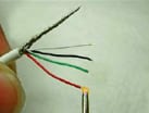
Red = + Excitation (input)
Black = - Excitation (input)
Green = + Signal (output)
White = - Signal (output)
Resistance measurements
It is recommended that a resistance check be made prior to installation. Check both the input (red and black) and output resistance (white and green). The resistance should be within ±20 ohms of the calibration certificate value. If the multimeter indicates an open or short on either input or output, the transducer should be considered inoperative. If the pressure transducer is out of specified range, it is necessary to apply an excitation voltage to the transducer. This voltage is specified on the calibration certificate and is a measure of the DC voltage on the output (green and white) leads. This value should be within ±10 mV of the original value and is called the Zero Measurand Output (ZMO). If the device is within the ZMO range, it should be considered good.
Conclusion
The aforementioned tests are not a substitute for actual calibration, though they will be useful for determining general pressure transducer operating conditions, thus reducing test data errors.