Question
My PR accelerometer seems to be broken. Is there any quick way to verify if it is an accelerometer or cable failure?
Answer
In acceleration shock measurements the two most destructive factors for an accelerometer are frequent excitations of its resonance, causing so called sensor ringing which may lead to the accelerometer's stain gauge fatigue, or cable whip, which may lead to its cable conductor's damage. In the case of a damaged cable, repair is possible. In the case of the actual accelerometer failure, there is no other option than accelerometer replacement.
When an accelerometer is determined to be non-operational, there is a way to identify the reason for the malfunction by differentiating between broken resistors (damaged Wheatstone bridge) and broken cable(s). In both cases the measurement of input and output impedance has to be carried out.
Cable failure:

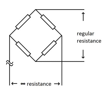
In the case of a cable failure, measurement of input and output impedance shall show the following results; the input or output impedance shall be infinite and the opposing one shall be just like the value indicated on the calibration certificate of the transducer. Sometimes, the damaged connection can be detected by flexing the cable at the body of the transducer or at the connector of the amplifier, the most likely locations for cable damage.
Piezoresistive transducer failure:

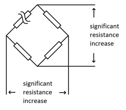
In the case of an accelerometer's internal Wheatstone Bridge (WB) structure failure, with respect to values given on the calibration certificate, a significant increase of input and output resistance readings is an indication of damage to the bridge elements. In the case of an intact WB, all the resistances connected together will have the appropriate value resistance. With one of them damaged, the circuit is partially broken, resulting in the input and output impedance doubling. In actuality, the resistances of the (WB) may not be equal (accelerometers featuring fixed resistors for shunt calibration, 7264B, 7264C, 7264H) therefore the damage to one of the bridge arms will result in substantial resistance increases that may be different for the transducer's input and output impedance measurement values.