Question
On most of your ISOTRON® accelerometer datasheets, a simple schematic is shown indicating how these accelerometers are to be powered up using a constant current source. A "decoupling capacitor" is always shown between the constant current source and output of the circuit. What is the function of this capacitor, and how is its value determined?
Answer
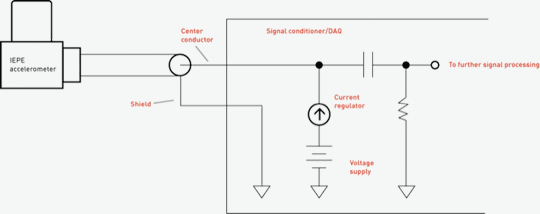
The decoupling capacitor you refer to is shown in the schematic (Figure 1). This capacitor strips off the DC bias voltage that comes from the ISOTRON® (IEPE type) accelerometer. This DC bias must be removed before the accelerometer's signal can be further processed; otherwise the signal would be railed out (distorted) if gained up, for example. This DC bias carries no useful information from the accelerometer (except, perhaps, that the accelerometer has been properly powered up).
It should be noted here that most modern IEPE signal conditioners and data acquisition (DAQ) systems already have the decoupling capacitor built in, so the user need not be concerned with determining its value. However, if you are building your own circuit, determining this capacitor value is straight-forward.
Whatever instrument you are connecting to this circuit (oscilloscope, DAQ, etc.) will have an input resistance that can be modeled as a single resistor across the output terminals. For an oscilloscope, this input resistance might be approximately 1 MΩ, for example. The decoupling capacitor, combined with the input resistance, forms an RC high pass filter, setting the low frequency corner of this circuit. It is important then, that the value of the capacitor is set such that the corner frequency is lower than the low frequency specification of the accelerometer, otherwise this circuit will be filtering out accelerometer data.
As an example, say you want the low frequency corner (-3dB) of this circuit to be 1 Hz. The input resistance is 1 MΩ. What does the capacitor value need to be? The formula to determine this is given by:
C = 1 / (2Ï€Rf)
Plugging in the values for frequency and resistance, capacitance comes out to be 0.159 µF. A 0.1 µF or 0.15 µF capacitor should be close enough, as input resistance is also not known accurately.
