Question
Our vibration control system and some of our data acquisition systems (DAQ) have a built-in IEPE current source. Is there any way that I would be able to isolate an accelerometer malfunction from a problem with my system electronics?
Answer
While most stand-alone IEPE (Isotron®) power supplies and amplifiers have some limited capabilities for accelerometer troubleshooting, most controllers and DAQ's lack these basic features. Here is a tip to help determine the condition of the accelerometer and the input signal in general.
First, it is recommended for any testing laboratory to have access to two basic pieces of test equipment, an oscilloscope and a digital multimeter (DMM). A simple analog oscilloscope is generally adequate.
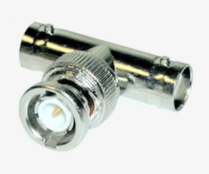
Most electronics use a BNC connector on the input, so the next step is to install a BNC "T" connector (see figure) to the instrument's accelerometer input connector. Connect the accelerometer to one leg of the connector "T" and attach another cable to the other side of the "T" and connect it to the oscilloscope and voltmeter.

Typical BNC "T" connector
With the accelerometer in a static state, read the DC voltage on the DMM. Now compare this voltage with the bias voltage specified on the accelerometer data sheet. The voltage should be within the specified range. If the accelerometer is at an elevated temperature, the bias might read lower than the specified range, which is normal. The bias voltage typically should never go below 7 VDC over the accelerometer's operating temperature range. Look for an instance where the voltage is near zero or considerably higher than the specified bias level. A very high voltage could be an accelerometer problem or, in most cases, indicative of an open cable. A low bias voltage (near zero volts) is indicative of a short in the cable or within the accelerometer itself.
If any of these abnormalities are observed, check cable connections. Disconnect the cable and check it with the Ohm meter to determine if there is an open or short. It is not recommended that the Ohm meter be used on the accelerometer since this could cause damage to the internal electronics.
The oscilloscope is used to observe the accelerometer output signal. With the accelerometer installed and a vibration signal applied, observe the signal and check for any clipping and distortion. With no vibration signal present, leave the accelerometer mounted and look for 60 Hz or other types of objectionable noise. The analog scope is recommended because it is easy to change sweep times and input levels in real time. The user doesn't have to be concerned with sampling rates when using the oscilloscope.
If the oscilloscope is AC coupled, the input capacitor will decouple the DC bias from the oscilloscope's input amplifier. Leaving the oscilloscope DC coupled will show both the AC signal and the DC bias. The DC coupled mode can also be used to measure accelerometer bias.