Question
I'm confused by the DC bias output voltage specification on your ISOTRON accelerometers, particularly as this voltage is shown to vary over temperature. Can you explain the significance of this specification and how it affects the user?
Answer
First it should be noted that if your data acquisition system (DAQ) is supplying the minimum specified supply voltage (sometimes called the compliance voltage) to the accelerometer, there usually is no reason to be concerned with the DC bias voltage. Even if your DAQ system doesn't supply the minimum supply voltage, often there is still no concern over DC bias voltage, if your accelerometer is operating at ambient temperatures.
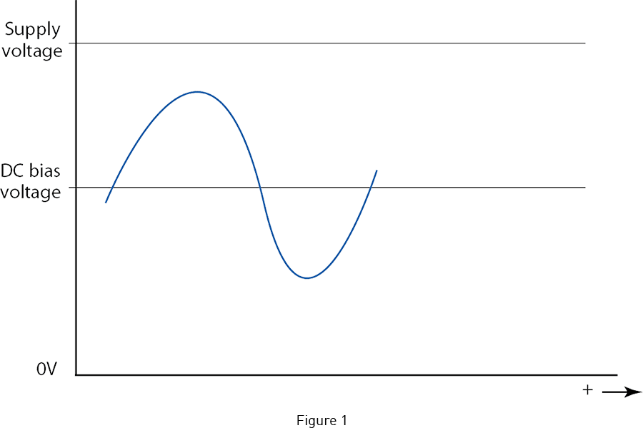
The signal from an ISOTRON (known generically as IEPE) accelerometer is a voltage signal, and as such, that voltage must "swing" between fixed voltage rails. In an ISOTRON system, those rails are 0 Vdc and the voltage of the supply voltage (the compliance voltage). This is illustrated in Fig 1. The DC bias voltage is established by the electronics inside the accelerometer. It serves as the "zero point" for the voltage signal, where the signal can swing above or below this zero. If the DC bias voltage changes (up or down), the zero will move with it.
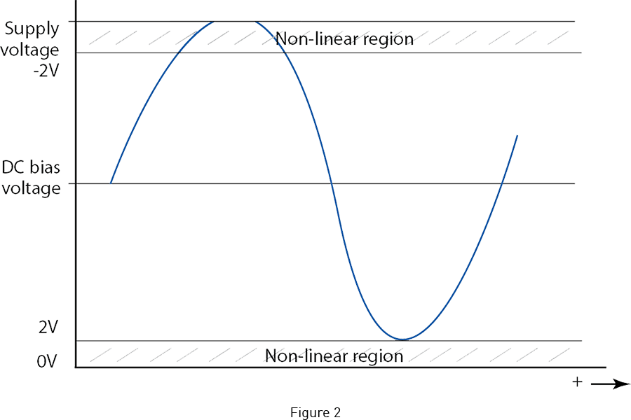
Now for distortion-free transmission of the signal, the signal must swing within the fixed rails. In fact, because of practical limitations in the internal electronics, the signal should not swing within 2 V of the rails. This is conservative, but swinging any closer to the rails risks entering the non-linear region of the internal electronics, potentially causing distortion. Certainly swinging to the rails, or past the rails, will cause saturation, or clipping, of the signal. See Fig 2.
For conventional ISOTRON accelerometers (there are some exceptions), full scale signal swing is ±5 V. In other words, for the accelerometer to achieve its rated full scale acceleration range (50 gpk, 500 gpk, etc.), the accelerometer's output signal must be able to swing up 5 V and swing down 5 V. [To illustrate this, signal swing can be calculated by multiplying the accelerometer's sensitivity by its full scale range. For example, a 50 gpk accelerometer will have a sensitivity of 100 mV/g: 100 mV/g x 50 gpk = 5 V. Another example: a 500 gpk accelerometer will have a sensitivity of 10 mV/g: 10 mV/g x 500 gpk = 5 V.]
Here is where the DC bias voltage comes in to play. As the DC bias (being the zero point of the signal) moves one way or the other, the risk increases that the signal will not be able to swing the full 5 V before running in to the rails. Depending on how much the DC bias moves, or if the supply voltage is lower than the minimum specified, this could become a real problem. For example, say an accelerometer has a DC bias voltage of 11 Vdc (a typical value) at ambient temperature. With a supply voltage of 18 Vdc, there would be no problem, because with a signal swing of 5 V, the signal peak would be right at 2 V away from the 18 V rail (starting at 11 V plus 5 V = 16 V). But say the DC bias moves up 3 V to 14 Vdc (due to exposure to temperature extreme, more on that below). With a supply voltage of just 18 Vdc, now you have a problem. Starting at 14 V and with a 5 V signal swing, the signal peak would be at 19 V and you would clip the signal. Now of course if you know you are not going to be exercising the full signal swing of the accelerometer, you may be able to get away with the 18 Vdc supply voltage. This is why we specify the worst case tolerance limits of the DC bias voltage; so that the user can make these choices if they know they are not supplying the minimum specified supply voltage. But again, note that with the minimum specified supply voltage, all these worst case limits have been considered. If supplied with the minimum supply voltage, the accelerometer will have no problem, even at the temperature limits.
What has not been explained here is why the DC bias voltage moves. First note that at room temperature, there is range specified for DC bias. This is simply the statistical distribution of values we expect in final product, based on component variations one expects from normal manufacturing tolerances. We test DC bias voltage at final calibration and will not ship a unit if it falls outside these limits. This tolerance range widens if the accelerometer is exposed to its full specified temperature range. This is mainly due to current leakages and voltage drifts in the internal electronics at temperatures beyond ambient. This range is guaranteed by design and you can be assured that the accelerometer will perform within these tolerance limits.